Motorcycle Brake Disk and Hub Adapters
- Torin Walker

- Mar 3, 2019
- 6 min read
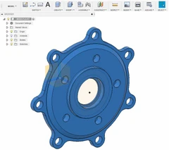
Customer asked me to make him a couple of brake-disc adapters and hub adapters for his motorcycle restoration project. Looked like a fun project!
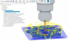
Starting with a 3D model provided by the customer, I generated CAM toolpaths to estimate the time it would take to machine and provided him with a quote.
Estimated machine time was initially thought to be 3 hours per brake-disk adapter plus about an hour to finish the other side on the manual lathe, and about an hour each for the hub nuts.
Using Fusion 360, I set the brake disk adapter in a block measuring 7 x 6.5 x 1.25 and started modeling toolpaths.

Using carbide cutters (for aluminum) I had on hand and selecting a diameter that balanced material removal with the need to get into the small areas between the bosses and the wall, I chose a 3/8" 3-flute aluminum endmill for the roughing pass. My mill isn't the greatest or most powerful either - only 3HP and 4k RPM, which limits the material removal rate for this diameter. I tried and tried, but couldn't get the time below 3 hours without pushing the small cutter beyond my comfort level.
The roughing pass initially calculated to 45 minutes or so, but was later slowed down even further. In fact, every estimate I came up with had to be extended by about 33% to prevent from breaking cutters or shifting the material. It's one thing to cut tens or hundreds of parts and to ramp up as one learns, but I only had one shot at this and the material (7075) was expensive - about $110 apiece, so I took it slowly.
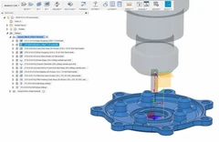
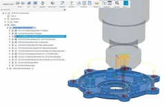
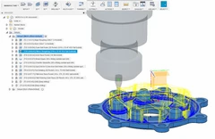
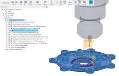
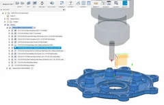
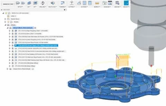
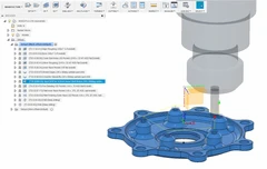
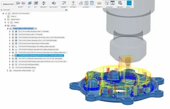
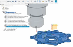
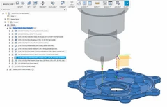
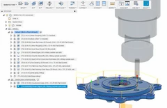
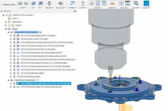
Gallery of operations above. Sorry, this blog doesn't easily allow me to create HTML tables with images in rows/columns. Will soon update this with better resolution pictures as well.
With the bulk of the operations above simulated, I was able to provide an estimate of the overall job (which included the time to set up these CAM operations.) My customer understood it would take time, but some customers don't realize that quoting jobs actually takes time and costs money.
With several emails back and forth to show the effect of the toolpaths and an esimate of the final costs, the customer committed sent an initial payment (50% to cover materials and time spent.)
Sourcing 7075 aluminum in this particular size (7 x 6.5 x 1.25) proved to be expensive since it did not fall within the dimensions of ordinary bar stock and had to be cut from plate. I had some pretty wild quotes from local suppliers ranging anywhere from $480 per piece down to $75 USD/per piece for large off-cuts from guys/shops off ebay.
We eventually settled on supplier from Quebec who offered $92 CAD/pc + $15 material report + $19 shipping + tax. Total material for the two pieces came to approximately $244, all in.
While waiting for the material to arrive, I developed a similar, smaller model to run on a piece of 6061 I had lying around. This was to test cutting speeds and to get a feel for the finish quality. After running the test, and breaking my only 1/8" endmill, I made some final adjustments to the customer's CAM model and was satisfied that I was prepared.
A week later, the material arrived and was cut 1/4" over the dimensions requested. I had to spend more time either trimming the parts to the modeled dimensions, or re-adjusting the CAM models. I chose the former and spent another hour milling the stock to the modeled size.

If you're wondering what the plastic is for, it's a vinyl shower curtain on a hoop-shaped rod surrounding the milling machine head that I can pull open/close to keep chips from flying everywhere. Ugly, but effective.
And finally, the real work begins:

This is always a frightening moment - one little mistake, and I have a $100 doorstop.

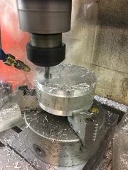
At this point, I know things are going to go well because it has finished ramping down in and is now cutting full load toward the edge. Fusion adjusts the feed throughout the program to ensure load on the cutter is consistent. At this point, I just follow the cutter with the shop-vac for the next four hours.

Lots of material coming off right now. An enclosure and chip conveyor would have made this operation a little more relaxiing, but sometimes mindless work (vacuuming, sweeping, turning stuff on a manual lathe) is a good way to take a load off.

During the last bit of the roughing operation, it increments downward to rough away some finer detail.


At this point, the roughing op is complete but on the next op, the 3/16 cutter was floating above the workpiece by about an inch. Seems when doing the tool heights I moved the decimal one spot too far to the left. It could have been worse and plunged into the material, breaking a cutter or worse, ruining the workpiece.
Fortunately, I just reset the tool height, re-ran the CAM generator (minus the roughing operation) and continued on my merry way.
I missed a bunch of shots at this point because I was hyper-focused on the operations to make sure I didn't screw up anything else.

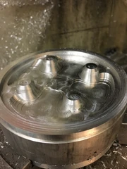
You may notice the fine detail milling around the bosses. You didn't miss much - just a couple of hours of very minimal material removal. Up until this point, I had just closed the curtains and let run until each new tool change.
Notice too the cylindrical pocket doesn't have a broken-off 1/8 endmill stuck in it :-)

This is the result of the first half of the part and and four hour's worth of machining. The outside contour could have been improved with a finishing pass, but this was my very first attempt using Fusion and it was a struggle to get it this far first time around.

What it looks like from the Linux CNC view. The overall program was 4.5 megabytes (iirc) and took a good minute to load. I was afraid it would puke, but Linux CNC is actually quite robust and dependable.

This brake disk adapter was actually quite difficult to hold. I thought initially I would hold it using the seven outer bolt-holes, but I ended up using the threaded stand-offs instead. Here I'm machining a fixture to put in the four-jaw chuck. If you notice the 0.16" offset from center, yeah... I couldn't figure out how to center the part within the stock. Until after I gave up, that is. The trick is to set the origin and click on any circular feature, then suddenly the stock centers on your model. Instead, I had to center it using the four-jaw. Same diff, but now I have a bunch of offset holes in what was otherwise a perfectly good chunk of 1015 steel.

Here, the adapter has been mounted and centered in the four jaw using the seal shoulder as a reference. Next, a hole drilled and bored as close as possible to the inside bore, then centered again using that reference. Finally, the material from the rectangle is carefully turned until round. On the second piece, I saved a lot of time by trimming the corners on the bandsaw. Should have thought of that first.

This often happens... I actually finished the first piece and forgot to take photos. I get so focused on the task... and this piece was intricate; the designer just had to make everything radiused, which meant I had to calculate the start and stop of every radiussed corner, turn up until those points, then create and blend the radii. I just didn't have time to take photos. I also drastically underestimated how long it would take to turn the other side of this piece because of those radii. I finished the second half of part #1 in a few (maybe three ~ four?) hours. The second piece went a lot faster. I did the second half of part #2 in under three hours. Another few hours lost to optimism.

Here I'm taking a photo of the completed part (completed lathe-work, anyway) before removing from the chuck. Last operation, again not photoed, is the chamfering.
Chamfering the second side is where I finally figured out how to center the stock in Fusion 360. Until this point, I was performing an air cut and noticing it wasn't following the contours. When I finally figured one can click on any reference in the model to adjust the origin point, the next generated GCode program properly followed the contours. I then gradually lowered the Z height until the mill/drill met with the edge of the part, watched it follow the contour exactly, then set the Z to the surface of the part and watched Fusion perform a perfect chamfer.
Takes a while to gain confidence in software driving one's machinery, but at this point, I am confident enough to trust Fusion will do what I tell it.
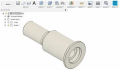
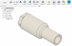
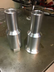
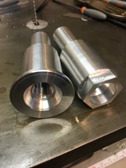
I apologize again, but somwhere in there, I banged out the two hub adapters and forgot to take pictures.
The whole project:

And a few more shots graciously provided by the customer:


The adapter on the wheel

The disk brake installed along with the hub adapter flange nut.

Nice glamour shot

And one happy customer (left.)
Until next time, keep spinning.
Torin...






Comments