Brown and Sharpe No. 13 Rear-Mount 2HP Motor Upgrade
- Torin Walker

- Jan 16, 2021
- 7 min read
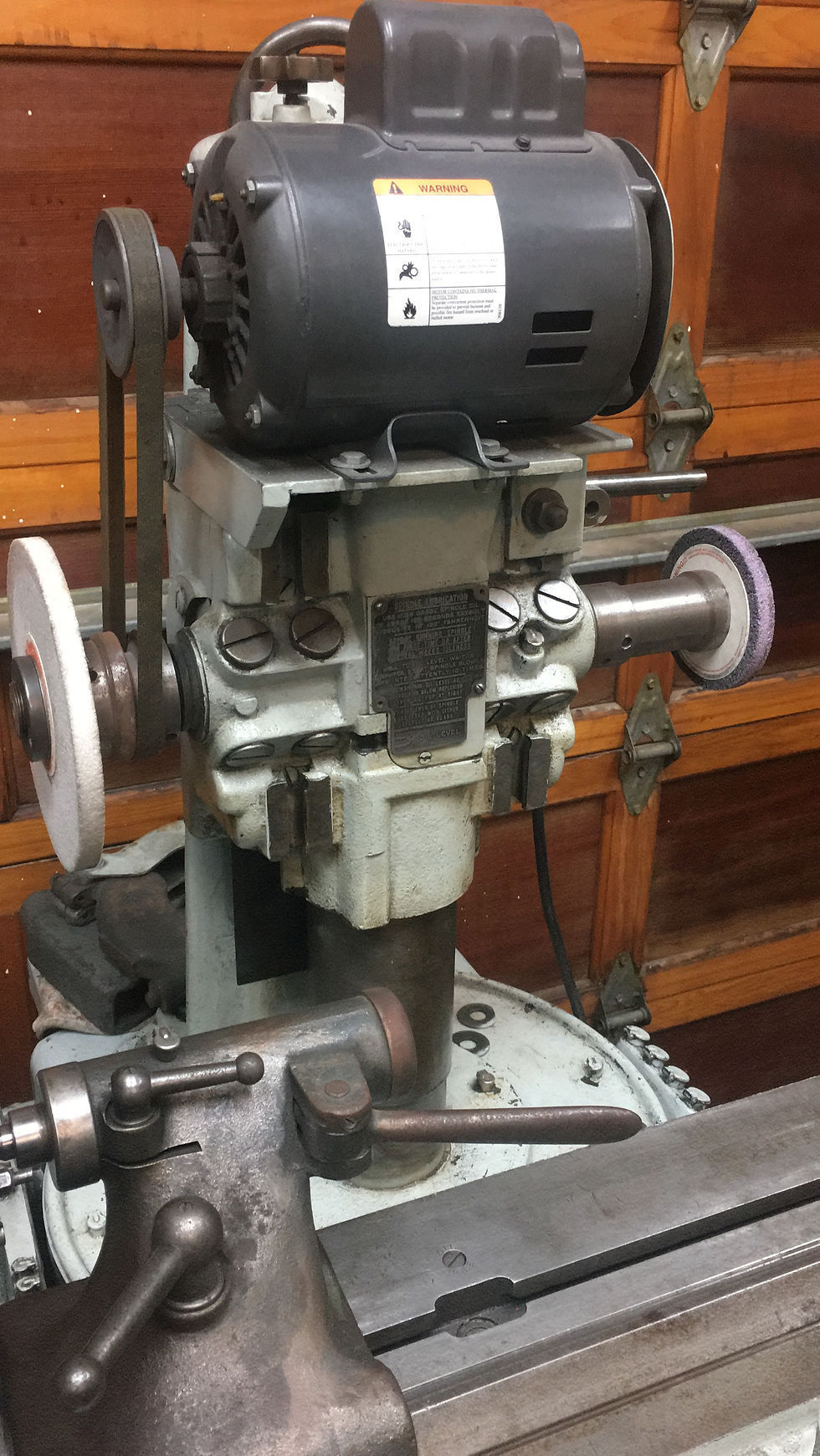
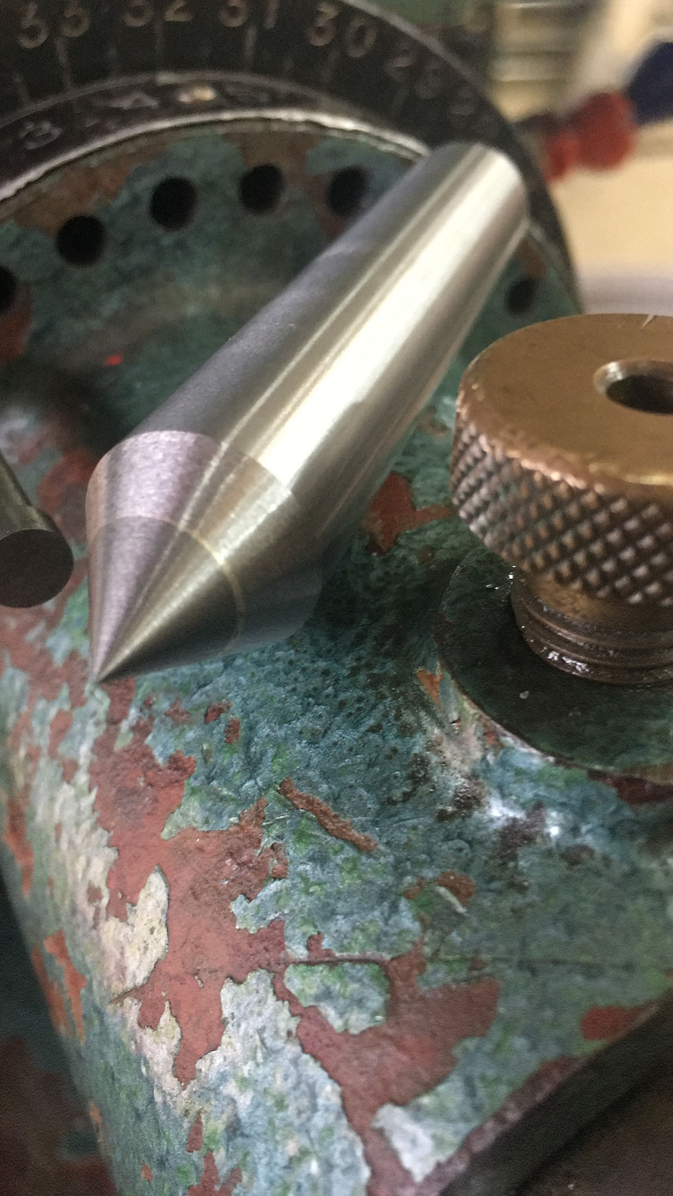
The 1943 Brown and Sharpe #13 Universal and Tool Grinder powers both the horizontal table feed and the column-mounted grinding spindle from a single 1-1/2HP motor located in the base. Power from this motor is routed to the table and spindle via separate sets of belts, pulleys, and tensioners. At some time in its past, my #13 had the spindle belt, pulleys and tensioners removed, replaced by an open-to-air 1/2 HP motor (shown above) with a piece of aluminum screwed to one end to keep the dust out. As if!
Time to get working on a replacement.
Newer models of the B&S 13 have a modified casting with a rear-mounted motor that drives the spindle from the right side using a combination pulley and RH-thread wheel mount. I will be building the same, except I will drive the spindle from the left side since I already have a LH combo pulley/wheel mount (also seen above).
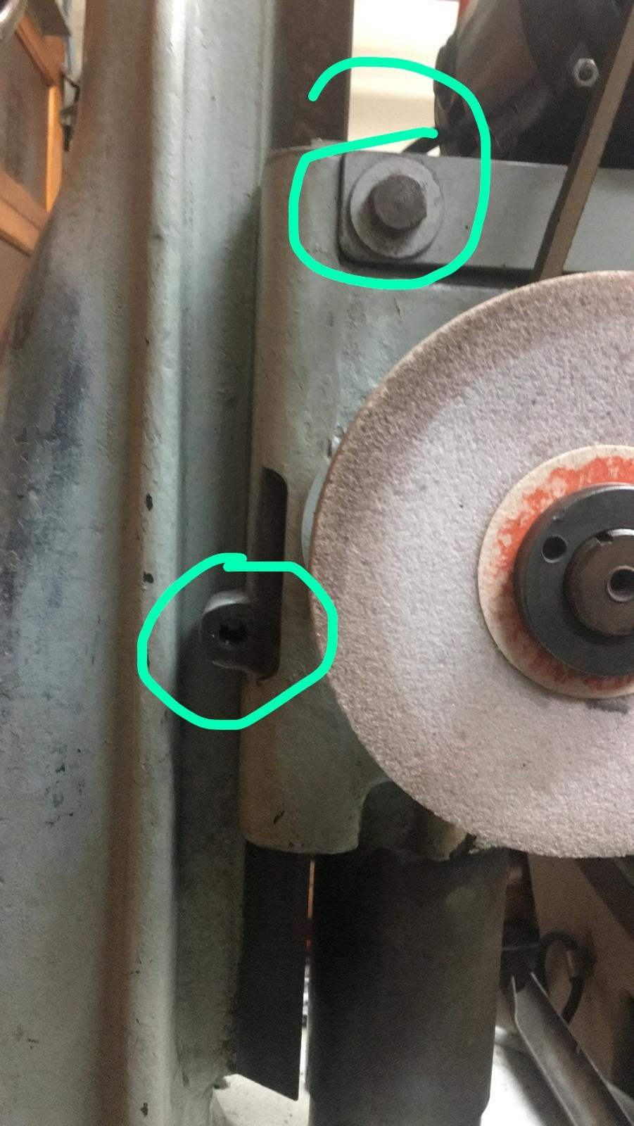
Mounting Points - there are two 1/2-14 (yes, 14 TPI) bolts holes on each side of the spindle casting intended to hold an offset arm for wheel guards. I will repurpose these to affix a custom motor base on which will sit a 2HP TEFC behind the column.
The base will consist of side plates bolted to the mount plates, a rear plate for the motor, and gussets to increase rigidity. This mock-up in Fusion 360 gives an idea of the final product:


The 1/2-14 bolts will actually double to mount the plates and serve as a point on which the wheel guards will fasten. More about wheel guards later.
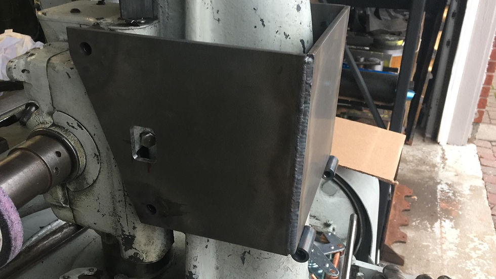
I measured the casting from each side, noting the recessed bolt location and compensated with stand-offs projecting inward from the side plates. I then cut the 1/4" plates, all to approximately 9-1/2 x 8". How convenient.
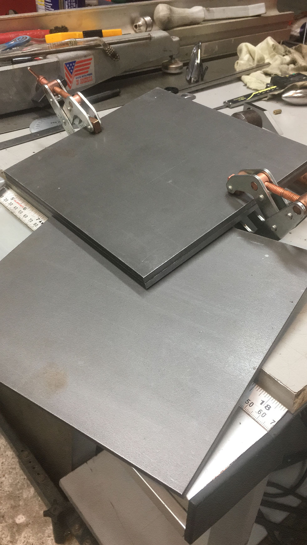
Side plates are clamped, marked, then drilled and reamed together to keep them symmetric.


The awkward position of the bolts, depressed and not at any obvious whole-fraction offset required me to take measurements several times to be absolutely sure. Measuring height and angle and a bit of Trig landed me spot on without having to enlargen the .500" holes. Wow.
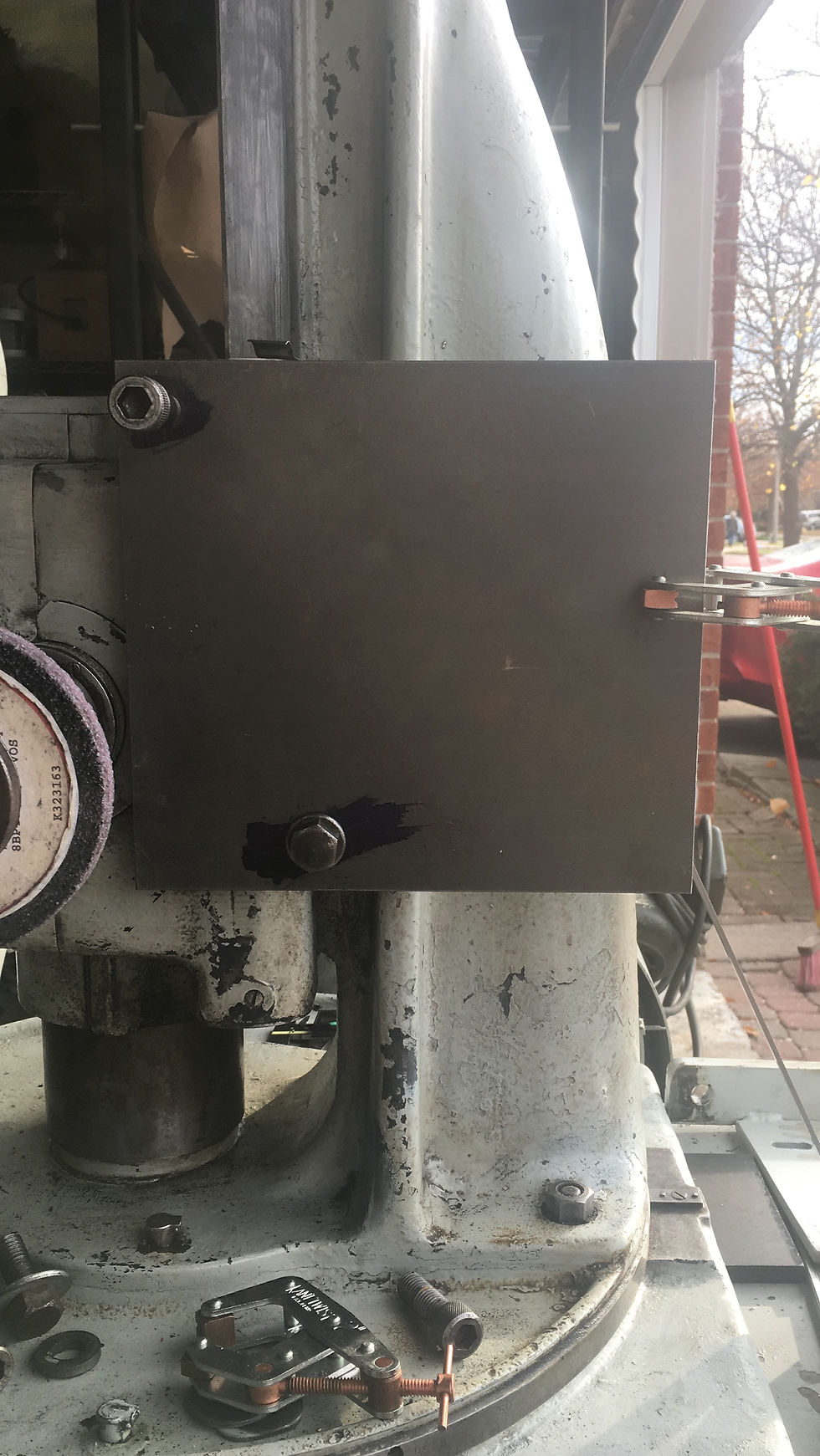
With the holes aligned, I make some standoffs and weld them up. You'll notice a couple of hinge points in the third and fourth pictures: After a few more test fittings, I realize that sliding the motor up and down on its mount isn't going to give me the range needed to accommodate belt lengths with integer inch increments. The 42" belt will be too tight, so I create a hinge and swinging mount plate to take up slack in the next sized belt.
I forgot to capture the backplate build, sorry. Suffice it to say it was a rod split into three, drilled through the outer two, and drilled and tapped on the inner third for a pair of 1/4 long socket head cap screws I had lying around. I drilled and tapped deep enough so the screws bottom out just before the head tightens up on the countersunk pivots, eliminating the need for nuts to capture the screw ends.


Here I test fit the motor to get an idea of the belt, pulley size, etc. This was actually an earlier shot, but sets up for the next step which is to get a properly sized pulley.
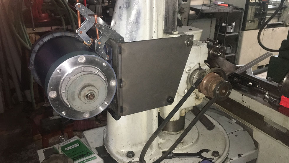
The pulley in the front measures 2.75", and the motor is 1725 RPM. Grinding wheels of the 7" and 8" size generally top out at 3600 rpm. So, I aim as close to that target as possible and find a standard 5.95" Type B pulley at Toronto Gears for a mere $27.00... except they won't sell me just one. Minimum order is $35. I call them and say, "Can you charge me $35 for a single pulley?" A woman on the other end says yes, but not today. A few days go by and I've still not heard from her. By then I've already purchased the steel. I'm going to make one instead.
Not to worry. This will be quick:


BOOM. I adjusted the pulley to 5.85" diam to get a theoretical 3500 rpm using an online pulley calculator and its advanced (more accurate) equation. For anyone who is curious, the groove is exactly 0.500 wide at the periphery, 0.625 deep and has 38 degree walls per the Machinery Handbook for a type B belt.
Here I test fit the motor by clamping to the swing plate and, after a quick run to Canadian Tire to pick up a variety of v-belts, I try it out. This one is way too tight, even before I put on the swing plate. The next size up is 43".

Next is to reinforce the box to prevent vibration. I cut up a cardboard template to fit around the column casting. I will use this to trace out the design on the top plate and will flip it to the other side to get a symmetric design.
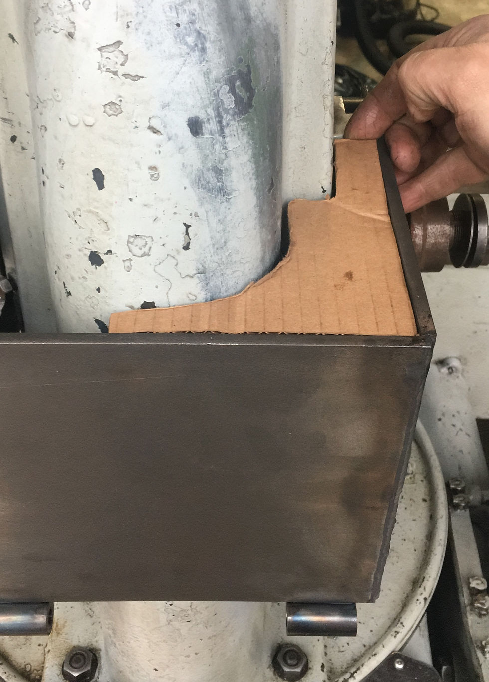
Unfortunately, my only 1/4 contouring bandsaw blade is broken so I had to cut out this template the hard way - on the mill, first by overlap drilling then releiving the support areas with an endmill. Off camera, I take to it with a jigsaw and clean it up on the belt sander.
After releiving all that stress, I straighten the thin bowed web on the Dake arbor press whereafter it fits perfectly with no gaps. I tack it into place.


One last adjustment: Upon switching to the next belt size, the motor swing plate angles out to about 7~8 degrees and takes up the slack, but is too taught. The motor weight alone doesn't give the right tension, so I change out the swing plate adjustment screws for longer ones and fabricate a few springs to dampen the vibrations. I can now adjust the ideal position of the plate between two springs. This needs some fine tuning, but does the job.

With the motor mount box complete, I start on a belt guard. I don't have any sheet-metal forming tools, so I weld up a makeshift v-block for the arbor press and use a piece of 3" diameter C1018 roundbar to shape the strip of 16ga steel into the profile shown below in picture 1 (top, left). The other parts were marked out using this outline as the template and cut in the bandsaw. Holes were cut using a holesaw on the manual mill.
Again, apologies... I failed to capture most of the making of this guard - The photos below are actually of my second attempt since the first guard was too close to the spindle on the return path to the motor, causing the belt to vibrate against the cover. I separated the belt guard pieces, reshaped and extended the profile to give more room near the spindle then tacked it back together.
I also improved the way the cover mounts by welding up the cover first, then using that cover to outline the profile of the back cover and "ridge" (for lack of a better term, bottom left) over which the cover fits. Again, sorry for the lack of pictures. When I captured these, I was showing a friend what I had going on, not thinking about producing a blog.
In picture three (bottom, left) once I fitted the ridge to fit within the perimiter of the cover, I tacked it to the the rear base plate (shown between my coffee cup and glasses) as a form-fitted assembly. Later I will drive screws through the cover into this ridge to hold it in place.


After all that work, and sitting proud with coffee cup in one hand, camera in the other, I tried putting on the wheel guards... no dice. No way to extend either of the four retaining bolts and get the guards to swing into place without interfering, so off comes the belt guard, and on goes the wheel guard. I might later cut up the belt guard and use only the rear half to protect around the motor pulley, but as it stands, there's too much going on up around the spindle.
Below, the far-more-important wheel guard is in place instead. I had to remake the lower 1/2-14 mount bolt to fit the factory L-shaped adjustable guard mount post and run the post between the belts. Perhaps I will cut the belt guard in half to at least protect the back half of the belt path, but not for this blog.

Lastly, I need to wire the motor to the machine. The B&S #13 conveniently has output connectors for the headstock motor on the left, and a coolant pump attachment on the right. Luckily they are rated for 10A which is perfect for the draw from a 2HP motor - about 7A.


It took me a while to fish around inside the machine and determine the make/model of the connector, but using the "Ever-Lok" brand name, the shape of the connector and the voltage/current ratings, and a lot of research, I managed to find a spec which led me to this listing on eBay for about $12 plus $15 for shipping:

Turns out these connectors are far more common than I thought, since after purchasing it on ebay, I saw them in a local electrical surplus store for more or less the same price. Anyway, it popped into place very nicely.

After trip to Home depot, I came back with SOW (rubber sheath) 12-3 flexible cable and elbow connector, then sat with my coffee and hooked it up.

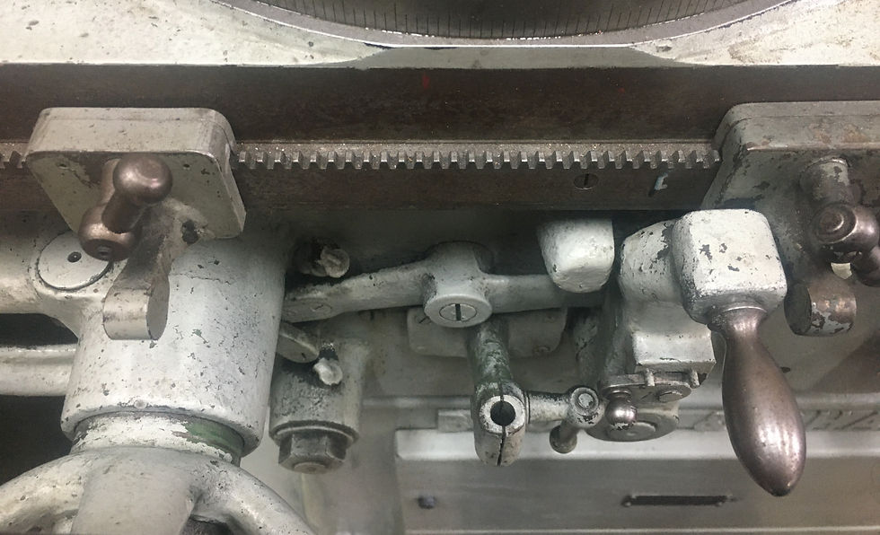
Now the moment arrives to try it out. I fire up the phase converter, wait for the power relay to engage, hit the switch and... nothing. Great, what's wrong now? I open up the electrical panel and start looking around. Tracing the path from the connector, poking around with the multimeter, I track conductivity across the breakers on one side, but not the other. One leg is down. I pull the heaters from the middle pair of tremperature-controlled relays and see the problem; one of them is corroded and broken off where the nichrome is brazed to the input (at least, it was disconnected upon inspection), and the other was melted. Not sure if I did this, but based on the look of it, I'd say this happened long ago. Anyway, these heaters are far too small for the current going through a 2HP motor, so I shorted each breaker across a little fusebox and tried the motor. It spun up... so definitely these heaters, or the whole relay needs to be replaced. Time to hunt for replacements.


These GE 81D heaters took a while to find too. I came across a spec for GE temperature-based relays and found several offered on eBay, but also found a local supplier showing stock in a few values suitable for the motor, as well as as other brands of relays about the same size. I found two GE 7A 81D heaters, and picked up a pair of Westinghouse relays just in case. After getting home the new 81D heaters did the trick and the motor fired up. I returned the westinghouse relays the next day. Total cost after returns: ~$20.
By this time, it's late into the evening, dark, around 10pm and I'm done. I spin it up.
Well that's all for now.
Torin...

Comments