B&S #13 Table Feed Stop Dogs
- Torin Walker

- Nov 21, 2021
- 6 min read
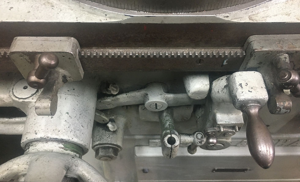
When I first started using the automatic table feed (shown above) I positioned each of two adjustable sliders until the table switched at the desired positions. It worked well enough, but two things bothered me: first, the paddles on these sliders never actually touched the table feed switch lever - instead, the root of each paddle caught the back edge of the lever instead. You can see a dark spot at the base (in the root of the weld) of the paddle where it catches the square block behind the actual lever handle.
Here is a closeup of what I'm talking about; it kinda kisses the corner down at the base of the paddle and back of the switch.

So something seemed off, like these paddles weren't the right part or had been repaired, or something. One of them even seemed to have been repaired, with more braze than the other, so it got me looking into why. The second and even more concerning aspect is that I had to really crank down hard on these guys to stop them from sliding when the contacted, potentially leading the spindle crashing into either the headstock or tailstock. A catastrophe no doubt as this purely mechanical movement had no safety mechanism to stop it other than running off the gear rack underneat that drives it. An exploding wheel at minimum, and bent spindle and headstock parts at worst.
I created a post on Practical Machinist showing this to other members, asking them to show pictures of their dogs for comparison. With no response, and lacking any original manuals for my particular version of (1943) machine, I started looking back at old sales brochures. Sure enough, I saw what I was looking for.

The adjustable sliders I am using (A) are actually micrometer stops. One per machine anyway. I ended up with two. A micrometer mounts in a little vertical bracket between the left handwheel and the switch lever that butts up against the paddle face of the stop. The actual dogs (B1, B2) meant to reverse the feed are more robust, and look like they fully engage the breadth of the reverse lever as one would expect. I zoom in to surmise how they might operate. Using this photo and the parts manual showing a spring plate, one can imagine how the dogs might operate.

It appears the dogs are hinged opposite the contact point and spring-loaded as if when pressed with the thumb, they lift up to disengage from the rack to be slid along the rack. When engaged and pressure applied, the downward angle drives the mechanism downward into the rack to ensure positive engagement. The fine feed looks as it it adjusts the range through this pivot, but that's just a guess.
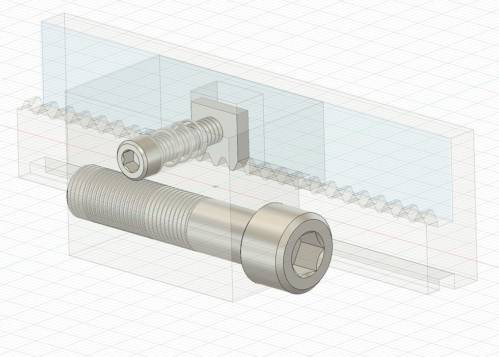
I ruminate over a number of designs like the above, all with that one important requirement in mind - positive rack engagement during switching - but it dawns upon me a simplified design employing a rectangular body with a T-slot, a toothed pawl that engages the rack via a spring-loaded plunger, plus a fine adjust screw. Below is my transparent mock-up of a push-button dog with fine adjustment in Fusion 360:
I only have one set of gear cutters on hand - a set of 16-pitch 14-1/2 PA chinese cutters that have collected dust ever since I bought them two years ago. I pull the No. 7 cutter (135 to ∞ ) and eyeball it against the rack. Imagine my surprise - it'll work. I check the pitch of the rack with my thread gauge and measure 5-TPI. I pull a little chunk of 4142 from the rack, clamp it in the vise, find the center, and start cutting four teeth (5 cuts) using depth guidelines in the Machinery Handbook. I saw them in two and try them out.
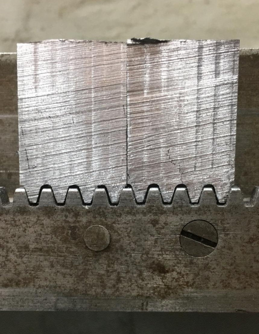
Now I have a nice little interface with the rack. I put them on the surface grinder to bring them down to the thickness of the table rack. Shown now out of sequence, I drill and tap them. I screwed up and drilled the second one (2nd photo, right pawl) with the clearance (.25) drill rather than the #7 drill, so I bump these up to 3/8 tapped holes instead.
For the body, I square up another chunk of 4142 large enough to accommodate a T-slot for the rack, a spring and plunger, the cross-wise adjustment screw, and will project out enough to give full engagement with the table reverse lever.
I measure the rack and mill the initial slot, then undercut the T-slot with a .1875 woodruff cutter. I had to run the woodruff cuter to within .005 of the shaft to provide enough clearance for the rack. I suspect this was as designed because the woodruff cutter exactly matches the slot width of the micrometer stops mentioned earlier. An endmill is used to mill out a pocket for the pawls. Sorry, I forgot to capture these moments.
The block now furnished with T-slot doesn't quite slide over the rack, so I relieve it with a file here and there until it travels from end to end.
I drill 1/4 holes through the center of the pockets, then bore from the front to accept a spring and the head of a socket-head cap screw.
Serendipitously, I ordered myself some piano wire from KBC Tools in sizes .051, .063, .071, .080, .091, .128 but I had my kids wrap them up as presents. These were among the items I chose as my Christmas presents from my wife. I sneaked the .051 out of the wrapping, clipped off a length, then repackaged it and put it back under the tree. I find having a variety of spring wires from about .040 up to .125 really handy, and I collect springs from everything i take apart - they come in handy all the time for fixing appliances, tools, and occasions just like this.
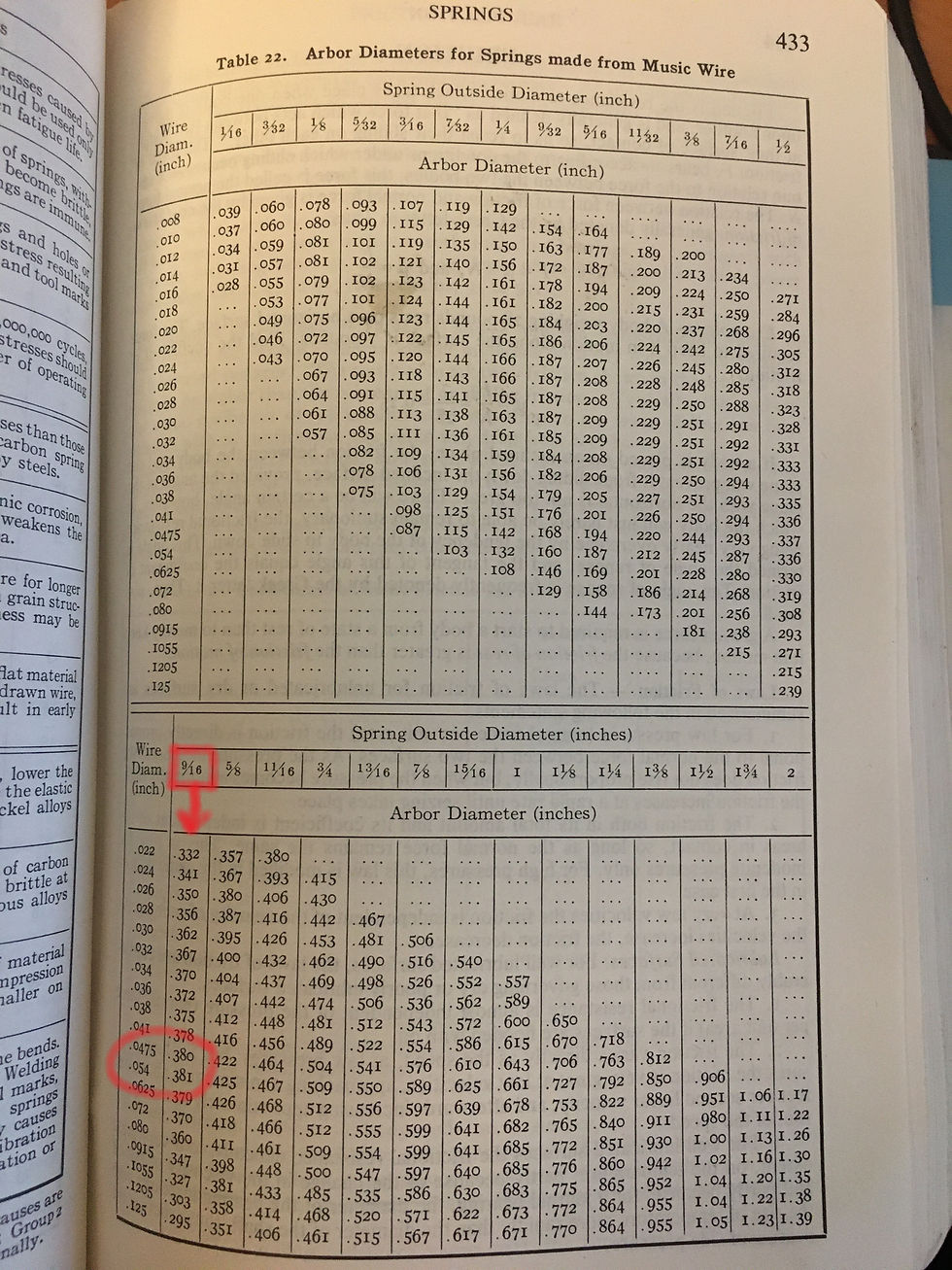
The Machinery Handbook has a handy reference that, for given a spring diameter and music wire size, provides an arbor size for winding. I am looking to make a 9/16 spring using .051 wire. I interpolate between the two wire sizes to get a .3805 mandrel. I turn down a 1/2 C1018 rod about two inches, cross-drill a .060 hole, and feed the wire through a little block drilled for .060 held in my toolholder. The next part is all done by turning the chuck by hand: I wind up the first two turns tightly, engaged the half-nut at 9-TPI and turn the rest. When I get to the number of turns I need, I disenage the feed and turn the last two coils tightly again, then clipped it off, gring the ends square, and repeated for the second spring.
This photo is actually borrowed from a "spindle inspection/repair" blog I have yet to write wherein I duplicate an existing spring that compresses a bearing against the spindle, but the springs I created for the dogs are exactly the same (as the spring on the left.)

I apologize for the pawls and the block being a little out of sequence. I am reconstructing this blog from photos I took earlier, and as I said before, I always seem to machine first, and blog later, so I'm missing a ton of crucial shots. So sorry.
The proper sequence is that I knew I had the right gear cutter, so I made the block first, then the pawls, then used the block to center and drill the pawls. Well, anyway, here's a few shots of me fitting the pawls before I had drilled them.

The block slotted and pawl pockets milled, with the freshly ground pawls being fitted for a slip-fit.

This is the pawl being shortened and relieved in the corners to fit into the pocket and match the height of the rack, shown left. Now we're back in synch with the sequence.
I put the pawls in the pockets and drilled through each, tap them for 3/8-16, then install the springs and screws.
(RIGHT) With the button depressed the pawl sits behind the rack teeth and is disengaged.
(LEFT) Spring tension keeps the pawl pulled in and engaged with the rack
A test fit on the rack before the dogs are separated. On the left is shown the "button" in the normal position, on the right is shown unscrewed to reveal the spring mechanism.

I split the block into two separate dogs, cross-drill for the adjustment screw, take a trip to Canadian Tire (it's always Saturday!) to pick up a pair M10 1.5x50's, then finish each screw by turning a knurled knob into which I press-fit the socket-head head cap screw.
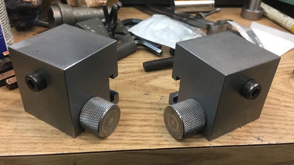
Finally, I give the new dogs a test. The buttons depress quite nicely, they disengage and re-engage easily, and though they wiggle a little on the rack (a little overzealous while relieving the T-slot, I guess), they are positively engaged with the rack and will stay put no matter what pressure is applied by the table feed against the switch lever. I can now rest easy knowing it won't crash during feed reversals.
They are ugly right now. I drew up some relief in Fusion 360 to see what they'd look like with radiussed corners, etc. One of these days, I will pull them off and remove some of the excess steel.
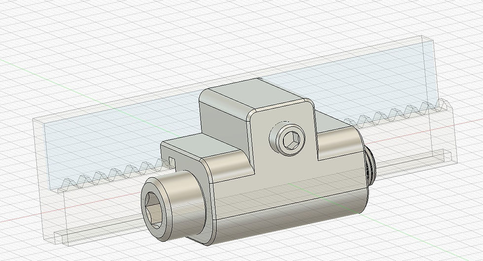
Something like this.
Except for making them pretty, here's a video of the finished project
Thanks for reading!
Torin...


Comments